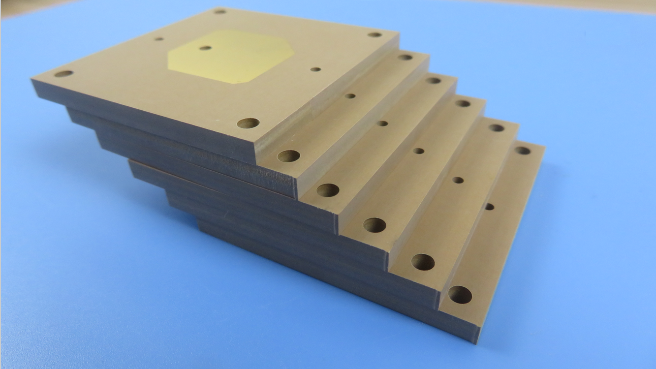
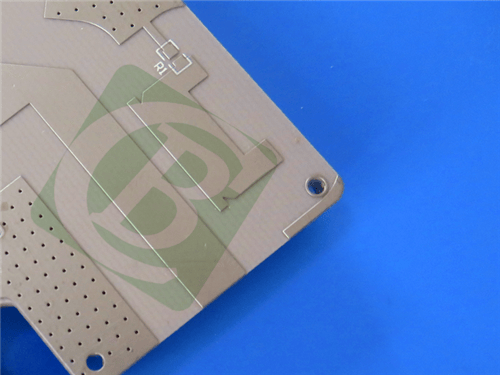
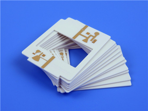
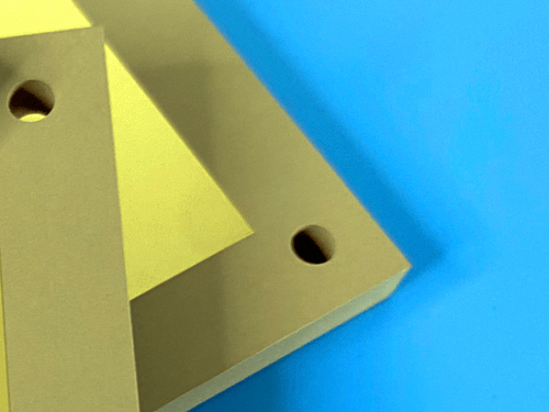
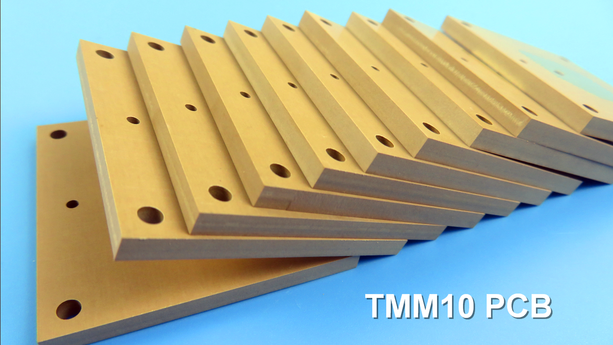
TMM10 2-Layer 0.5mm ENEPIG PCB – Microwave PCB for Antenna & Satellite
1.Introduction to TMM10 PCB
TMM 10 thermoset microwave materials offer the benefits of both PTFE and ceramic based substrates, but are not limited by the same mechanical properties and production techniques. This makes them an ideal choice for high-frequency and high-reliability applications where consistent dielectric performance and dimensional stability are critical. The TMM10 material system is specifically engineered to support demanding RF and microwave circuits, providing a robust alternative to conventional PTFE-based laminates without sacrificing electrical performance.
2.TMM10 Key Features
Dielectric Constant (Dk) of 9.20 +/- .230 Dissipation factor of .0022 at 10GHz Thermal coefficient of Dk of -38 ppm/°K Coefficient of thermal expansion matched to copper Decomposition Temperature (Td) of 425 °C TGA Coefficient of Thermal Expansion - x y z : 21ppm/K, 21ppm/K, 20ppm/K Thermal Conductivity of 0.76W/mk Available in a thickness range of .0015 to .500 inches +/- .0015"
3.TMM10 Key Benefits
Mechanical properties resist creep and cold flow Resistant to process chemicals, reducing damage during fabrication Material does not require a sodium napthanate treatment prior to electroless plating Based on a thermoset resin, allowing for reliable wire-bonding
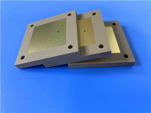
4.TMM10 PCB Construction Details
| Item | Specification |
|---|
| Base material | TMM10 |
| Layer count | Double sided |
| Board dimensions | 76mm x 118mm = 1PCS, +/- 0.15mm |
| Minimum Trace/Space | 4/6 mils |
| Minimum Hole Size | 0.35mm |
| Blind vias | No |
| Finished board thickness | 0.5mm |
| Finished Cu weight | 1oz (1.4 mils) outer layers |
| Via plating thickness | 20 μm |
| Surface finish | ENEPIG |
| Top Silkscreen | White |
| Bottom Silkscreen | No |
| Top Solder Mask | Green |
| Bottom Solder Mask | No |
| 100% Electrical test | Used prior to shipment |
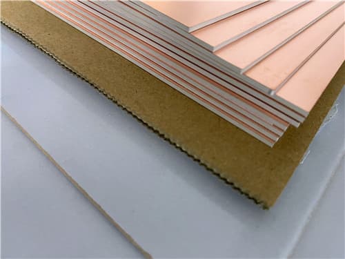
5.PCB Stackup (2-Layer Rigid Structure)
Copper_layer_1 - 35 μm
Rogers TMM10 Core - 0.381 mm (15 mil)
Copper_layer_2 - 35 μm
6.PCB Statistics
Components: 21
Total Pads: 45
Thru Hole Pads: 31
Top SMT Pads: 14
Bottom SMT Pads: 0
Vias: 29
Nets: 2
7.Primary Application Areas
Chip testers
Dielectric polarizers
Satellite communication systems
GPS antennas, and patch antennas etc.
8. Quality Assurance
Artwork supplied: Gerber RS-274-X
Accepted standard: IPC-Class-2
Availability: Worldwide
9.TMM10 High Frequency Materials
TMM® thermoset microwave materials are ceramic, hydrocarbon, thermoset polymer composites designed for high plated-thru-hole reliability stripline and microstrip applications. TMM laminates are available in a wide range of dielectric constants and claddings.
The electrical and mechanical properties of TMM laminates combine many of the benefits of both ceramic and traditional PTFE microwave circuit laminates, without requiring the specialized production techniques common to these materials. TMM laminates do not require a sodium napthanate treatment prior to electroless plating.
TMM laminates have an exceptionally low thermal coefficient of dielectric constant, typically less than 30 ppm/°C. The material's isotropic coefficients of thermal expansion, very closely matched to copper, allow for production of high reliability plated through holes, and low etch shrinkage values. Furthermore, the thermal conductivity of TMM laminates is approximately twice that of traditional PTFE/ceramic laminates, facilitating heat removal.
TMM laminates are based on thermoset resins, and do not soften when heated. As a result, wire bonding of component leads to circuit traces can be performed without concerns of pad lifting or substrate deformation.
TMM laminates combine many of the desirable features of ceramic substrates with the ease of soft substrate processing techniques. TMM laminates are available clad with 1/2 oz/ft² to 2 oz/ft² electrodeposited copper foil, or bonded directly to brass or aluminum plates. Substrate thicknesses of 0.015" to 0.500" are available. The base substrate is resistant to etchants and solvents used in printed circuit production. Consequently, all common PWB processes can be used to produce TMM thermoset microwave materials.
10.Features and Benefits
Features:
Wide range of dielectric constants Exceptional mechanical properties Coefficient of thermal expansion matched to copper Resistant to process chemicals Thermoset resin
Benefits:
Ideal for single material systems on a wide variety of applications Resist creep and cold flow High reliability of plated through holes Reduces damage to material during fabrication and assembly processes Reliable wirebonding No specialized production techniques required TMM10 and 10i laminates can replace alumina substrates
11.TMM10 Data Sheet
| Property | Typical Value | Direction | Units | Conditions | Test Method |
|---|
| Dielectric Constant (process) | 9.20 ± 0.230 | Z | - | 10 GHz | IPC-TM-650 method 2.5.5.5 |
| Dielectric Constant (design) | 9.8 | - | - | 8 GHz – 40 GHz | Differential Phase Length Method |
| Dissipation Factor (process) | 0.0022 | Z | - | 10 GHz | IPC-TM-650 method 2.5.5.5 |
| Thermal Coefficient of Dielectric Constant | -38 | - | ppm/°K | -55 to +125°C | IPC-TM-650 method 2.5.5.5 |
| Insulation Resistance | >2000 | - | Gohm | C/96/60/95 | ASTM D257 |
| Volume Resistivity | 2×10⁸ | - | Mohm·cm | - | ASTM D257 |
| Surface Resistivity | 4×10⁷ | - | Mohm | - | ASTM D257 |
| Electrical Strength (dielectric strength) | 285 | Z | V/mil | - | IPC-TM-650 method 2.5.6.2 |
| Decomposition Temperature (Td) | 425 | - | °C TGA | - | ASTM D3850 |
| Coefficient of Thermal Expansion - x | 21 | X | ppm/K | 0 to 140°C | ASTM E 831 / IPC-TM-650, 2.4.41 |
| Coefficient of Thermal Expansion - y | 21 | Y | ppm/K | 0 to 140°C | ASTM E 831 / IPC-TM-650, 2.4.41 |
| Coefficient of Thermal Expansion - z | 20 | Z | ppm/K | 0 to 140°C | ASTM E 831 / IPC-TM-650, 2.4.41 |
| Thermal Conductivity | 0.76 | Z | W/m/K | 80°C | ASTM C518 |
| Copper Peel Strength after Thermal Stress | 5.0 (0.9) | X,Y | lb/inch (N/mm) | after solder float 1 oz. EDC | IPC-TM-650 Method 2.4.8 |
| Flexural Strength (MD/CMD) | 13.62 | X,Y | kpsi | A | ASTM D790 |
| Flexural Modulus (MD/CMD) | 1.79 | X,Y | Mpsi | A | ASTM D790 |
| Moisture Absorption (1.27mm / 0.050") | 0.09 | - | % | D/24/23 | ASTM D570 |
| Moisture Absorption (3.18mm / 0.125") | 0.20 | - | % | D/24/23 | ASTM D570 |
| Specific Gravity | 2.77 | - | - | A | ASTM D792 |
| Specific Heat Capacity | 0.74 | - | J/g/K | A | Calculated |
| Lead-Free Process Compatible | YES | - | - | - | - |
12.Some Typical Applications
RF and microwave circuitry Power amplifiers and combiners Filters and couplers Satellite communication systems Global Positioning Systems Antennas Patch Antennas Dielectric polarizers and lenses Chip testers
|